|
|
|

Ever
wondered what the acronym USB stands for? Well it stands for Universal Serial
Bus. Prior to the existence of the USB various other standards existed like
the RS-232 Serial port and the LPT Printer port, but the common problems faced
by most of these interfaces were like speed limit and the number of devices
that can be connected simultaneously. These old interfaces served most of
peripheral commutations for decades, as the computing needs of then did not
demand for anything better that a mere 20-115kbps. The parallel port could of
course support up to 8Mbps but owing to its large port/cable size and a maximum
connectivity of 8 devices it really didn’t pull on. What was needed was a
communication port, which had a small port size and can address relatively a
large number of devices. In the early 90’s many manufacturer specific standards
like the HP Interface Bus (HPIB) and the Centronics interface were also
released but were incompatible with other systems.
Taking all the problems under consideration Developers from
companies like Compaq, HP, Intel, Lucent, Microsoft, NEC, and Philips gathered
together and formed the USB Implementers forum. The USB 1.0 Specifications was
launched in the year 1996 following which in 1998 the USB 1.0 specifications
were released which the problems of the earlier 1.0 version had been fixed.
By 1998 we saw many of the PC motherboards came with USB
1.1 support. April 2000 marked the release of the USB 2.0 specifications with
an a new high speed option, an later that year a new MINI D connector was
defined which use to connect on to the peripheral side. Later all mother board
manufacturers started giving USB ports on their products.
The main added feature in the USB 2.0 was the added High
speed transfer which could go up to a whooping 480 Kbps, which is about 40
times higher that, the earlier USB 1.1. USB 2.0 is fully backward compatible
with USB 1.x (i.e. USB 1.0 and USB 1.1) only that the hub used should be that
of USB 2.0 specifications.
Inside the PC we have a Host controller and a Root Hub that
work in combination with the operating system to communicate with devices on
the bus. The host controller translates outgoing and incoming data onto the
desired USB specification format and also manages transfers between the various
devices connected to it. The root hub has one or more connectors (the ones we
see on the backside of the motherboard), which connect to devices. The Root Hub
along with the host controller detects the attachment and removal of devices.
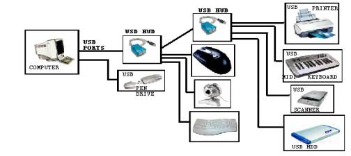
Each hub can connect to a maximum of 127 devices (see
figure). Now at this point a doubt might arise that ‘I have only two USB ports
on my mother board, Can I still connect 127 devices to it ’. The answer is yes
but how it is achieved is what we will be seeing now. The USB uses a tired star
topology, which means that each device has to be connected to the root hub
either directly or through another hub. A Hub can be connected to another hub
that can be connected to another series of devices until 127 devices are
connected. Basically speaking they are all just parallel connections. You must
be wondering how all 127 devices are managed. Well the fact is that one root
hub is allotted one and only one IRQ and the rest of the communication with the
other device data transfer is managed by the host controller using a technique
similar to time splicing.
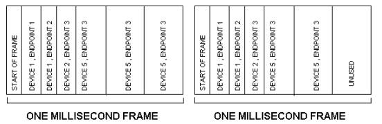
The Host controller manages data transfer by dividing time
into chunks called frames. The host gives each transfer a small portion of each
frame, for low speed devices frames are 1ms but for High speed transfers (only
supported by USB2.0) the frames are
125-microsecond frames. A transfer cosmists of one or more number of
transactions. A transaction will be in the from of multiple frames. Since all
devices share a common data path each transaction should contain a device
address and an endpoint. The USB host controller assigns a unique address to
each device that gets connected to it. The device in itself will have a
controller in it, which will understand this address and store it in an
internal register. The device when connected also supplies the host with
information as to what kind of a device it is and what kind of data transfer it
needs. Based on the application the device might have one or more endpoints (an
endpoint means a destination on the device which can access or send data).
Getting confused lately, check out the figure it may help simplify things.
Hence the host controller initiates all transfers. It is an
always pull type data transfer where is the host controller pulls data from the
devices and the devices respond only when asked to.
In short the data transfer can be summarized as below:
The user plugs in the device onto a USB portà
the HUB detects the deviceàthe host learns about the device,
assigns it and address, learns about the data endpoints loads the device
drivers, establishes a communication pipe*, initiates transfer àthe
device simply responds to the host’s requests and either sends or receives data
from the Host.
There are a lot more details involved in the communication
but unfortunately it does not fall within the scope of this article. I hope the above information was useful in
understanding the basics if USB Transfers.
kvpnet@inbox.com
References:
1.The USB Implementers forum official webpage www.usb.org.
2. http://www.crucial.com/library/understanding_usb.asp
3. http://www.everythingusb.com/forums/forumdisplay.php?forumid=4
* USB pipe isn’t a
physical object; it’s just a software association between a device’s endpoint
and the host controller’s software.